FPGA之HDMI显示
HDMI 显示
在 上一篇博文中,我们介绍了 HDMI 编码部分,在本篇博文中,我们将完成完成 HDMI 后续的任务:HDMI 的串行发送以及完整显示。
ODDR
时钟选择
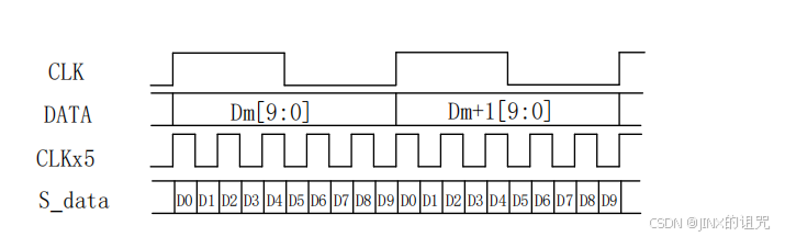
在发送阶段,我们通常使用 5 倍的编码器的时钟工作频率,发送编码的 10 位数据。原因很简单,在使用 DDR 的情况下(时钟的上升沿和下降沿都起作用时),在 clk_5x 频率下,串行发送 10 位数据的时间大致与编码部分在 clk 下处理 10 位数据时间相同,有利于实现数据的同步。
模板使用
在 FPGA 中,我们可以使用 现成的 DDR 模板 来完成。
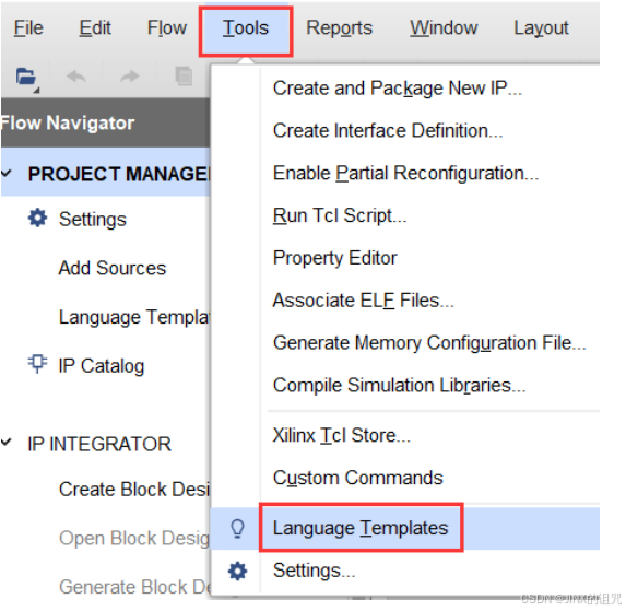
点击 Tool 栏,找到 Language Templates。
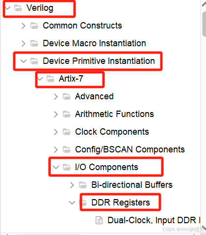
在 Verilog 的 Device Primitive Instantiation 中找到 Artixe-7 系列;点击 I/O Componets, 找到 DDR Registers.
我们需要串行输出编码数据,因而使用 ODDR(Output DDR Register); 选择 ODDR 栏,在左边可以看见预览部分模板代码,根据需要复制即可。
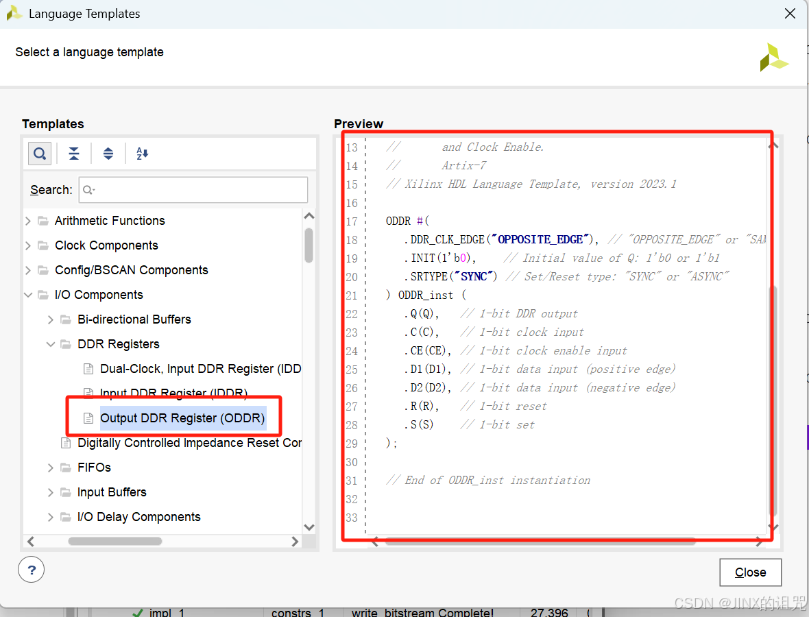
注: 需要根据自己使用 FPGA 芯片系列经行模板库的选择,切勿按图索骥。
端口介绍
ODDR 结构图如下
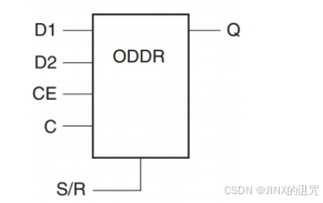
端口介绍如下表:
| 端口信号名 | I/O | 位宽 | 描述 |
|---|---|---|---|
| C | I | 1 | 输入时钟 |
| CE | I | 1 | 时钟使能 |
| D1 | I | 1 | 高段输入 |
| D2 | I | 1 | 低段输入 |
| S/R | I | 1 | 置位/复位 |
| Q | O | 1 | 输出 |
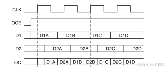
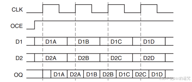
此处,我们说明一下 ODDR 的两个工作模式:Opposite Edge 和 Same Edge。
Opposite Edge 模式下,输入数据在时钟信号的上升沿被锁存,并在下降沿输出;同时,下一个输入数据在时钟信号的下降沿被锁存,并在下一个上升沿输出。此模式下,输出传输延迟低,数据恢复更容易,但功耗较高,对时钟的质量要求也很高。
Same Edge 模式下,输入数据在同时在时钟信号的上升沿或下降沿被锁存,并在上升沿和下降沿都输出**。 这种模式下,输出数据的两个边沿对应同一个输入数据。该方法可以简化时序设计,方便控制。对时钟要求低,功耗较低,但是延迟较高。
DDR 接口与 TMDS 数据为对应关系
我们使用 FPGA 中的 ODDR 核,进行 TMDS 数据发送
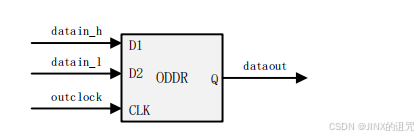
HDMI 共有 4 个通道,其中 3 个通道为数据通道,一个通道为时钟。每个通道需要在 5 个时钟周期内,完成 10 位数据输出。由于输出数据从低位开始,因而需要每个时钟周期就切换一次给 datain_h 和 datain_1。具体对应关系如下:

OBUFDS
由于 TMDS 编码方式在传输过程中,使用的差分传输方式,即对每一个通道都是用两根信号线,其传输电平刚好相反,为了实现此功能。我们可以使用 OBUFDS 模板库,使用方法同 ODDR 相同,在此就不多赘述。
代码
串行发送部分
`timescale 1ns / 1ps

module Ser_Def_10to1(
    input clk_x5,
    input [9:0] datain_0,
    input [9:0] datain_1,
    input [9:0] datain_2,
    input [9:0] datain_3,

    output wire dataout_0_n,
    output wire dataout_0_p,
    output wire dataout_1_n,
    output wire dataout_1_p,
    output wire dataout_2_n,
    output wire dataout_2_p,
    output wire dataout_3_n,
    output wire dataout_3_p
    );

 //模5计数器,用于选择数据位
 reg[2:0]TMDS_CNT5=0;

//移位寄存器
 reg[4:0]TMDS_Shift_0h=0, TMDS_Shift_01=0;
 reg[4:0]TMDS_Shift_1h=0, TMDS_Shift_11=0;
 reg[4:0]TMDS_Shift_2h=0, TMDS_Shift_21=0;
 reg[4:0]TMDS_Shift_3h=0, TMDS_Shift_31=0;


 wire [4:0] TMDS_0_1 = {datain_0[9],datain_0[7],datain_0[5],datain_0[3],datain_0[1]};
 wire [4:0] TMDS_0_h = {datain_0[8],datain_0[6],datain_0[4],datain_0[2],datain_0[0]};

 wire [4:0] TMDS_1_1 = {datain_1[9],datain_1[7],datain_1[5],datain_1[3],datain_1[1]};
 wire [4:0] TMDS_1_h = {datain_1[8],datain_1[6],datain_1[4],datain_1[2],datain_1[0]};

 wire [4:0] TMDS_2_1 = {datain_2[9],datain_2[7],datain_2[5],datain_2[3],datain_2[1]};
 wire [4:0] TMDS_2_h = {datain_2[8],datain_2[6],datain_2[4],datain_2[2],datain_2[0]};

 wire [4:0] TMDS_3_1 = {datain_3[9],datain_3[7],datain_3[5],datain_3[3],datain_3[1]};
 wire [4:0] TMDS_3_h = {datain_3[8],datain_3[6],datain_3[4],datain_3[2],datain_3[0]};


//5倍速率发送数据
always @(posedge clk_x5)begin
    //TMDS_CNT5[2]第一次为1时,刚好记到100为4,0到4-->>记了5个数
    TMDS_CNT5     <=(TMDS_CNT5[2])? 3'd0:TMDS_CNT5+3'd1;
    TMDS_Shift_0h <=(TMDS_CNT5[2])?TMDS_0_h:TMDS_Shift_0h[4:1];
    TMDS_Shift_01 <=(TMDS_CNT5[2])?TMDS_0_1:TMDS_Shift_01[4:1];
    TMDS_Shift_1h <=(TMDS_CNT5[2])?TMDS_1_h:TMDS_Shift_1h[4:1];
    TMDS_Shift_11 <=(TMDS_CNT5[2])?TMDS_1_1:TMDS_Shift_11[4:1];
    TMDS_Shift_2h <=(TMDS_CNT5[2])?TMDS_2_h:TMDS_Shift_2h[4:1];
    TMDS_Shift_21 <=(TMDS_CNT5[2])?TMDS_2_1:TMDS_Shift_21[4:1];
    TMDS_Shift_3h <=(TMDS_CNT5[2])?TMDS_3_h:TMDS_Shift_3h[4:1];
    TMDS_Shift_31 <=(TMDS_CNT5[2])?TMDS_3_1:TMDS_Shift_31[4:1];

end


wire dataout_0,data_out1,data_out2,dataout_3;


//使用ODDR 和OBUFDS
//Channel 0
 ODDR #(
      .DDR_CLK_EDGE("OPPOSITE_EDGE"), // "OPPOSITE_EDGE" or "SAME_EDGE"
      .INIT(1'b0),    // Initial value of Q: 1'b0 or 1'b1
      .SRTYPE("SYNC") // Set/Reset type: "SYNC" or "ASYNC"
   ) ODDR_0 (
      .Q(dataout_0),   // 1-bit DDR output
      .C(clk_x5),   // 1-bit clock input
      .CE(1'b1), // 1-bit clock enable input
      .D1(TMDS_Shift_01[0]), // 1-bit data input (positive edge)
      .D2(TMDS_Shift_0h[0]), // 1-bit data input (negative edge)
      .R(1'b0),   // 1-bit reset
      .S(1'b0)    // 1-bit set
   );

OBUFDS #(
      .IOSTANDARD("DEFAULT"), // Specify the output I/O standard
      .SLEW("SLOW")           // Specify the output slew rate
   ) OBUFDS_0 (
      .O(dataout_0_p),     // Diff_p output (connect directly to top-level port)
      .OB(dataout_0_n),   // Diff_n output (connect directly to top-level port)
      .I(dataout_0)      // Buffer input
   );

//Channel 1
 ODDR #(
      .DDR_CLK_EDGE("OPPOSITE_EDGE"), // "OPPOSITE_EDGE" or "SAME_EDGE"
      .INIT(1'b0),    // Initial value of Q: 1'b0 or 1'b1
      .SRTYPE("SYNC") // Set/Reset type: "SYNC" or "ASYNC"
   ) ODDR_1 (
      .Q(dataout_1),   // 1-bit DDR output
      .C(clk_x5),   // 1-bit clock input
      .CE(1'b1), // 1-bit clock enable input
      .D1(TMDS_Shift_11[0]), // 1-bit data input (positive edge)
      .D2(TMDS_Shift_1h[0]), // 1-bit data input (negative edge)
      .R(1'b0),   // 1-bit reset
      .S(1'b0)    // 1-bit set
   );

OBUFDS #(
      .IOSTANDARD("DEFAULT"), // Specify the output I/O standard
      .SLEW("SLOW")           // Specify the output slew rate
   ) OBUFDS_1 (
      .O(dataout_1_p),     // Diff_p output (connect directly to top-level port)
      .OB(dataout_1_n),   // Diff_n output (connect directly to top-level port)
      .I(dataout_1)      // Buffer input
   );


//Channel 2
 ODDR #(
      .DDR_CLK_EDGE("OPPOSITE_EDGE"), // "OPPOSITE_EDGE" or "SAME_EDGE"
      .INIT(1'b0),    // Initial value of Q: 1'b0 or 1'b1
      .SRTYPE("SYNC") // Set/Reset type: "SYNC" or "ASYNC"
   ) ODDR_2 (
      .Q(dataout_2),   // 1-bit DDR output
      .C(clk_x5),   // 1-bit clock input
      .CE(1'b1), // 1-bit clock enable input
      .D1(TMDS_Shift_21[0]), // 1-bit data input (positive edge)
      .D2(TMDS_Shift_2h[0]), // 1-bit data input (negative edge)
      .R(1'b0),   // 1-bit reset
      .S(1'b0)    // 1-bit set
   );

OBUFDS #(
      .IOSTANDARD("DEFAULT"), // Specify the output I/O standard
      .SLEW("SLOW")           // Specify the output slew rate
   ) OBUFDS_2 (
      .O(dataout_2_p),     // Diff_p output (connect directly to top-level port)
      .OB(dataout_2_n),   // Diff_n output (connect directly to top-level port)
      .I(dataout_2)      // Buffer input
   );

//Channel 3
 ODDR #(
      .DDR_CLK_EDGE("OPPOSITE_EDGE"), // "OPPOSITE_EDGE" or "SAME_EDGE"
      .INIT(1'b0),    // Initial value of Q: 1'b0 or 1'b1
      .SRTYPE("SYNC") // Set/Reset type: "SYNC" or "ASYNC"
   ) ODDR_3 (
      .Q(dataout_3),   // 1-bit DDR output
      .C(clk_x5),   // 1-bit clock input
      .CE(1'b1), // 1-bit clock enable input
      .D1(TMDS_Shift_31[0]), // 1-bit data input (positive edge)
      .D2(TMDS_Shift_3h[0]), // 1-bit data input (negative edge)
      .R(1'b0),   // 1-bit reset
      .S(1'b0)    // 1-bit set
   );

OBUFDS #(
      .IOSTANDARD("DEFAULT"), // Specify the output I/O standard
      .SLEW("SLOW")           // Specify the output slew rate
   ) OBUFDS_3 (
      .O(dataout_3_p),     // Diff_p output (connect directly to top-level port)
      .OB(dataout_3_n),   // Diff_n output (connect directly to top-level port)
      .I(dataout_3)      // Buffer input
   );

endmodule
HDMI 发送器
只要将编码器例化并与图像数据流数据和控制信号按照 HDMI 的协议链接到一起即可实现发送器模块。
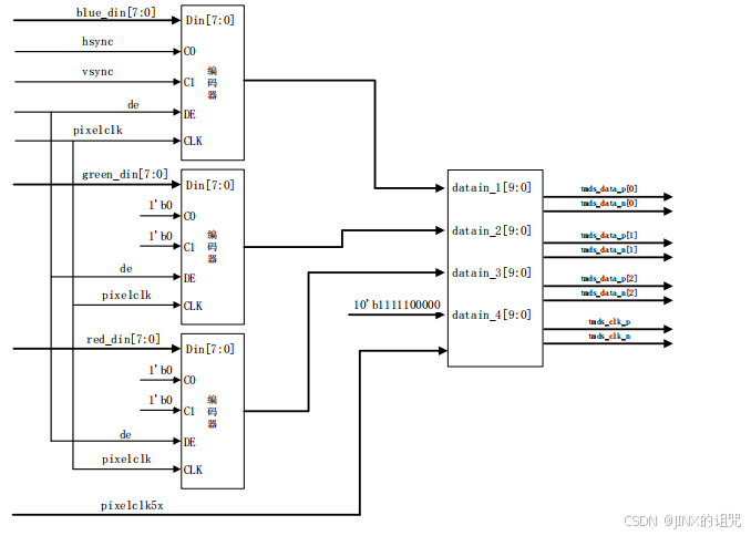
TMDS 在发送数据时,会将像素时钟(我们记为 tmds_clk)一起发送, tmds_clk 应该与与像素时钟 pixelclk 频率一致,而不是 pixelclk_x5。tmds_clk 用于同步一个完整的编码数据,而不是单个数据位。
产生 tmds_clk 有两种方式:一是将 pixelclk 取反;一是将使用 ODDR,以数据的形式产生。我们使用ODDR以数据的形式生成,此方法能在一定程度上,保持输出时钟和输出数据的相位关系,便于接收端经行同步。产生波形的方式很简单:我们让ODDR的输入段赋值10’b11111_00000,这样,在前2.5个时钟周期,输出电平为高,后2.5个周期输出电平为低。
HDMI发送器代码
`timescale 1ns / 1ps

module HDMI_Encoder(
    //输入全局控制信号
    input pixelclk,
    input pixelclk_x5,
    input rst_p,

    //输入显示数据
    input [7:0]blue_din,
    input [7:0]green_din,
    input [7:0]red_din,

    //输入显示控制信号
    input hsync,
    input vsync,
    input de,

    //输出
    output tdms_clk_p,
    output tdms_clk_n,
    output [2:0] tmds_data_p,
    output [2:0] tmds_data_n
    );

wire [9:0]red;
wire [9:0]green;
wire [9:0]blue;

//调用模块
Encode  encb(
   .clk(pixel_clk),    //像素时钟
   .rst_n(~rst_p),
   .din(blue_din),
   .c0(hsync),    //控制信号
   .c1(vsync),
   .de(de),  //数据使能
   .dout(blue)   //数据输出
);

Encode  encg(
   .clk(pixel_clk),    //像素时钟
   .rst_n(~rst_p),
   .din(green_din),
   .c0(1'b0),    //控制信号
   .c1(1'b0),
   .de(de),  //数据使能
   .dout(green)   //数据输出
);
Encode  encr(
   .clk(pixel_clk),    //像素时钟
   .rst_n(~rst_p),
   .din(red_din),
   .c0(1'b0),    //控制信号
   .c1(1'b0),
   .de(de),  //数据使能
   .dout(red)   //数据输出
);
Ser_Def_10to1  HDMI_Sender(
  .clk_x5(pixelclk_x5),
  .datain_0(blue),
  .datain_1(green),
  .datain_2(red),
  .datain_3(10'b11111_00000),
  .dataout_0_n(tmds_data_p[0]),
  .dataout_0_p(tmds_data_n[0]),
  .dataout_1_n(tmds_data_p[1]),
  .dataout_1_p(tmds_data_n[1]),
  .dataout_2_n(tmds_data_p[2]),
  .dataout_2_p(tmds_data_n[2]),
  .dataout_3_n(tmds_clk_n),
  .dataout_3_p(tmds_clk_p)
);

endmodule
注:Encode模块代码,见我的上一篇文章
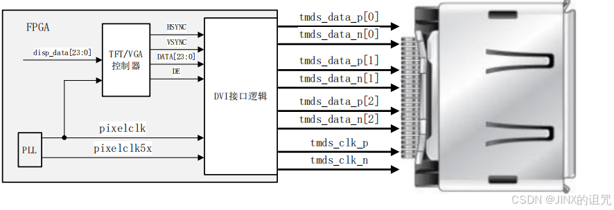
在完成该控制器之后,在使用时,只需要基于VGA或者TFT显示系统,将对应信号接到HDMI_Encoder 对应端口上即可
顶层
HDMI_Disp
`timescale 1ns / 1ps


module HDMI_Disp(
    input clk_50M,
    input rst_n,

    // HDMI1 interface
    output hdmi1_clk_p,
    output hdmi1_clk_n,
    output [2:0]hdmi1_dat_p,
    output [2:0]hdmi1_data_n,
    output [2:0]hdmi1_oe,

    // HDMI2 interface
    output hdmi2_clk_p,
    output hdmi2_clk_n,
    output [2:0]hdmi2_dat_p,
    output [2:0]hdmi2_data_n,
    output [2:0]hdmi2_oe,

    // HDMI3 interface
    output hdmi3_clk_p,
    output hdmi3_clk_n,
    output [2:0]hdmi3_dat_p,
    output [2:0]hdmi3_data_n,
    output [2:0]hdmi3_oe,

    //TFT interface
    output [15:0]TFT_rgb,
    output TFT_hs,
    output TFT_vs,
    output TFT_clk,
    output TFT_de,
    output TFT_pwn
    );
 //Resolution_800x480    //时钟为33MHz
 parameter
       Disp_Width =800,
       Disp_Height=480;

  wire pixelclk;
  wire pixelclk_x5;
  wire pll_locked;

  wire rst_p;
  wire [11:0] disp_h_addr;
  wire [11:0] disp_v_addr;
  wire disp_data_req;
  wire [23:0]disp_data;
  wire disp_hs;
  wire disp_vs;
  wire [7:0]disp_red;
  wire [7:0]disp_green;
  wire [7:0]disp_blue;
  wire disp_de;
  wire disp_pclk;

  assign rst_p = ~pll_locked;


  pll pll
(
    .clk_out1(pixelclk),     // output   33M
    .clk_out2(pixelclk_x5),     // output 165M
    .resetn(rst_n), // input resetn
    .locked(pll_locked),       // output locked
    .clk_in1(clk_50M)      // input clk_in1
);

 Color_Bar #(
 .Disp_Width(  Disp_Width),
 .Disp_Height( Disp_Height)
 ) color_bar (
    .disp_h_addr(disp_h_addr),
    .disp_v_addr(disp_v_addr),
    .disp_data_req(disp_data_req),
    .disp_data(disp_data)
);

Disp_Driver disp_driver(
    .clk_disp    (  pixelclk      ),
    .rst_p       (  rst_p         ),
    .Data_In     (  disp_data     ),
    .DataReq     (  disp_data_req ),
    .H_Addr      (  disp_h_addr   ),
    .V_Addr      (  disp_v_addr   ),
    . Disp_Hs    (  disp_hs    ),
    . Disp_Vs    (  disp_vs     ),
    . Disp_Red   (  disp_red    ),
    . Disp_Green (  disp_green  ),
    . Disp_Blue  (  disp_blue   ),
    . Frame_Begin(             ), //一帧图像开始的标志符号
    . Disp_De    ( disp_de    ),
    . Disp_Pclk  ( disp_pclk  )
    );

  //TFT
  assign TFT_rgb = {disp_red[7:3],disp_green[7:2],disp_blue[7:3]};
  assign TFT_hs  = disp_hs;
  assign TFT_vs  = disp_vs;
  assign TFT_clk = disp_pclk;
  assign TFT_de  = disp_de;
  assign TFT_pwm = 1'b1;


 HDMI_Encoder  encoder1(
    //输入全局控制信号
  .pixelclk    (pixelclk   ) ,
  .pixelclk_x5 (pixelclk5x ) ,
  .rst_p       (reset_p    ) ,
  .blue_din    (disp_blue  ) ,
  .green_din   (disp_green ) ,
  .red_din     (disp_red   ) ,
  .hsync       (disp_hs    ) ,
  .vsync       (disp_vs    ) ,
  .de          (disp_de    ) ,
  .tdms_clk_p  (hdmi1_clk_p) ,
  .tdms_clk_n  (hdmi1_clk_n) ,
  .tmds_data_p (hdmi1_dat_p) ,
  .tmds_data_n (hdmi1_dat_n)
    );

 assign hdmi1_oe = 1'b1;

 HDMI_Encoder  encoder2(
    //输入全局控制信号
  .pixelclk    (pixelclk   ) ,
  .pixelclk_x5 (pixelclk5x ) ,
  .rst_p       (reset_p    ) ,
  .blue_din    (disp_blue  ) ,
  .green_din   (disp_green ) ,
  .red_din     (disp_red   ) ,
  .hsync       (disp_hs    ) ,
  .vsync       (disp_vs    ) ,
  .de          (disp_de    ) ,
  .tdms_clk_p  (hdmi2_clk_p) ,
  .tdms_clk_n  (hdmi2_clk_n) ,
  .tmds_data_p (hdmi2_dat_p) ,
  .tmds_data_n (hdmi2_dat_n)
    );

assign hdmi2_oe = 1'b1;

endmodule
辅助模块
Color_Bar
`timescale 1ns / 1ps

module Color_Bar #(
     parameter Disp_Width = 800,
     parameter Disp_Height= 480
)(
    input [11:0]disp_h_addr,
    input [11:0]disp_v_addr,
    input disp_data_req,
    output reg [23:0] disp_data
);

 localparam
    BLACK    = 24'h000000, //黑色
    BLUE     = 24'h0000FF, //蓝色
    RED      = 24'hFF0000, //红色
    PURPPLE  = 24'hFF00FF, //紫色
    GREEN    = 24'h00FF00, //绿色
    CYAN     = 24'h00FFFF, //青色
    YELLOW   = 24'hFFFF00, //黄色
    WHITE    = 24'hFFFFFF; //白色

  //定义每个像素块的默认显示颜色值
  localparam
    R0_C0 = BLACK,   //第0行0列像素块
    R0_C1 = BLUE,    //第0行1列像素块
    R1_C0 = RED,     //第1行0列像素块
    R1_C1 = PURPPLE, //第1行1列像素块
    R2_C0 = GREEN,   //第2行0列像素块
    R2_C1 = CYAN,    //第2行1列像素块
    R3_C0 = YELLOW,  //第3行0列像素块
    R3_C1 = WHITE;   //第3行1列像素块

	wire [3:0]row_act;
	wire [1:0]col_act;

genvar i ,j;
	localparam  row_height= Disp_Height/4,
	            col_width=  Disp_Width/2;
  for (i=0;i<4;i=i+1)begin
    assign row_act[i]=(disp_v_addr>=i*row_height)&&(disp_v_addr<(1+i)*row_height);
  end
  for (j=0;j<2;j=j+1)begin
    assign col_act[j]=(disp_h_addr>=j*col_width)&&(disp_h_addr<(1+j)*col_width);
  end

always@(*)
		case({row_act,col_act,disp_data_req})
			7'b0001_01_1:disp_data = R0_C0;
			7'b0001_10_1:disp_data = R0_C1;
			7'b0010_01_1:disp_data = R1_C0;
			7'b0010_10_1:disp_data = R1_C1;
			7'b0100_01_1:disp_data = R2_C0;
			7'b0100_10_1:disp_data = R2_C1;
			7'b1000_01_1:disp_data = R3_C0;
			7'b1000_10_1:disp_data = R3_C1;
			default:disp_data = R0_C0;
		endcase

endmodule
Disp_Driver
`include "disp_para.vh"


module Disp_Driver(
    input clk_disp,
    input rst_p,

    input [`Red_Bits +`Green_Bits + `Blue_Bits -1:0]Data_In,
    output DataReq,

    output [11:0]H_Addr,
    output [11:0]V_Addr,

    output reg Disp_Hs,
    output reg Disp_Vs,
    output reg [`Red_Bits-1:0]Disp_Red,
    output reg [`Green_Bits-1:0]Disp_Green,
    output reg [`Blue_Bits-1:0]Disp_Blue,
    output reg Frame_Begin, //一帧图像开始的标志符号
    output reg Disp_De,
    output Disp_Pclk
    );
   //连线
    wire hcount_ov;     // 行计数器溢出信号
    wire vcount_ov;     // 列计数器溢出信号


    reg [11:0]hcount_r;  // 行计数寄存器
    reg [11:0]vcount_r;  // 列计数寄存器

    `ifdef HW_VGA
        assign Disp_Pclk=~clk_disp;
    `else
        assign Disp_Pclk= clk_disp;
    `endif

    assign DataReq =Disp_De;

parameter   Hdata_Begin = `H_Sync_Time + `H_Back_Porch + `H_Left_Border - 1'b1,
            Hdata_End   =  `H_Total_Time - `H_Right_Border - `H_Front_Porch-1'b1,
            Vdata_Begin = `V_Sync_Time + `V_Back_Porch + `V_Top_Border-1'b1,
            Vdata_End   = `V_Total_Time - `V_Bottom_Border - `V_Front_Porch-1'b1,
            VGA_HS_End  = `H_Sync_Time - 1'b1,
            VGA_VS_End  = `V_Sync_Time - 1'b1,
            Hpixel_End  = `H_Total_Time - 1'b1,
            Vline_End   = `V_Total_Time - 1'b1;


      // 行计数器溢出信号
    assign hcount_ov = (hcount_r >= Hpixel_End);  // 行计数器达到最大值时,溢出信号有效


    // 行计数器
    always @(posedge clk_disp or posedge rst_p) begin
        if(rst_p)          // 复位时,行计数器清零
            hcount_r <= 0;
        else if (hcount_ov)  // 达到行扫描结束位置时,行计数器清零
            hcount_r <= 0;
        else                // 否则,行计数器加1
            hcount_r <= hcount_r +1;
    end


      // 列计数器溢出信号
    assign vcount_ov = (vcount_r >= Vline_End);  // 列计数器达到最大值且行计数器溢出时,溢出信号有效

    // 列计数器
    always @(posedge clk_disp or posedge rst_p) begin
        if(rst_p)          // 复位时,列计数器清零
            vcount_r <= 0;
        else if(hcount_ov) begin  // 行计数器溢出时,列计数器递增
            if(vcount_ov)  // 达到列扫描结束位置时,列计数器清零
                vcount_r <= 0;
            else                // 否则,列计数器加1
                vcount_r <= vcount_r + 1;
        end
        else vcount_r<=vcount_r;
    end

  // 数据有效区标志
    always @(posedge clk_disp)begin
        Disp_De <= ((hcount_r >= Hdata_Begin) && (hcount_r < Hdata_End)) &&
                   ((vcount_r >= Vdata_Begin) && (vcount_r < Vdata_End));  // 当行计数和列计数都位于有效数据区域时,数据有效区标志有效
    end


    assign H_Addr = Disp_De?(hcount_r - Hdata_Begin):12'd0;
    assign V_Addr = Disp_De?(vcount_r - Vdata_Begin):12'd0;


    always @(posedge clk_disp)begin
        Disp_Hs <= (hcount_r >= VGA_HS_End);  // 行计数器大于等于 VGS_HS_End 时,行同步信号有效
        Disp_Vs <= (vcount_r >= VGA_VS_End);  // 列计数器大于等于 VGS_VS_End 时,场同步信号有效
       {Disp_Red,Disp_Green,Disp_Blue} <=(Disp_De) ? Data_In :0;  // 在数据有效区输出RGB数据,否则输出黑色
    end


  reg Disp_Vs_Dly1; //用于提取上升沿
  always@(posedge clk_disp)
  begin
    Disp_Vs_Dly1 <= Disp_Vs;
  end

  always @(posedge clk_disp or posedge rst_p)begin
    if(rst_p)begin
        Frame_Begin<=0;
    end else if(!Disp_Vs_Dly1&&Disp_Vs)begin
        Frame_Begin<=1;
    end else begin
        Frame_Begin<=0;
    end//else
  end

endmodule
头文件
disp_para.vh
/*使用说明
使用时根据实际工作需求选择2个预定义参数就可以

参数1: MODE_RGBxxx
预定义用来决定驱动工作在16位模式还是24位模式,二选一
  MODE_RGB888:24位模式
  MODE_RGB565:16位模式
  4.3寸TFT显示屏------使用16位色RGB565模式
  5寸TFT显示屏--------使用16位色RGB565模式
  GM7123模块----------使用24位色RGB888模式

参数2: Resolution_xxxx
预定义用来决定显示设备分辨率,常见设备分辨率如下所述

4.3寸TFT显示屏:
  Resolution_480x272

5寸TFT显示屏:
  Resolution_800x480

VGA常见分辨率:
  Resolution_640x480
  Resolution_800x600
  Resolution_1024x600
  Resolution_1024x768
  Resolution_1280x720
  Resolution_1920x1080
*/

//也可通过宏定义显示设备类型来进行设置,选择一个使能,其他使用注释的方式屏蔽
//使用4.3寸480*272分辨率显示屏
//`define HW_TFT43

//使用5寸800*480分辨率显示屏
`define HW_TFT50

//使用VGA显示器,默认为640*480分辨率,24位模式,其他分辨率或需16位模式可在代码63行至75行进行重配置
//`define HW_VGA

//=====================================
//以下宏定义选择用于根据显示设备进行位模式和分辨率2个参数的设置
//=====================================
`ifdef HW_TFT43  //使用4.3寸480*272分辨率显示屏
  `define MODE_RGB565
  `define Resolution_480x272 1 //时钟为9MHz

`elsif HW_TFT50  //使用5寸800*480分辨率显示屏
  `define MODE_RGB565
  `define Resolution_800x480 1 //时钟为33MHz

`elsif HW_VGA    //使用VGA显示器,默认为640*480分辨率,24位模式
//=====================================
//可选择其他分辨率和16位模式,需用户根据实际需求设置
//代码75~76行设置位模式
//代码77~83行设置分辨率
//=====================================
  //`define MODE_RGB565
  `define MODE_RGB888
  //`define Resolution_640x480   1 //时钟为25.175MHz
  //`define Resolution_800x480   1 //时钟为33MHz,可兼容TFT5.0
  //`define Resolution_800x600   1 //时钟为40MHz
  //`define Resolution_1024x600  1 //时钟为51MHz
  //`define Resolution_1024x768  1 //时钟为65MHz
  `define Resolution_1280x720  1 //时钟为74.25MHz
  //`define Resolution_1920x1080 1 //时钟为148.5MHz
`endif

//=====================================
//非特殊需求,以下内容用户不需修改
//=====================================
//定义不同的颜色深度
`ifdef MODE_RGB888
  `define Red_Bits   8
  `define Green_Bits 8
  `define Blue_Bits  8

`elsif MODE_RGB565
  `define Red_Bits   5
  `define Green_Bits 6
  `define Blue_Bits  5
`endif

//定义不同分辨率的时序参数
`ifdef Resolution_480x272
  `define H_Total_Time    12'd525
  `define H_Right_Border  12'd0
  `define H_Front_Porch   12'd2
  `define H_Sync_Time     12'd41
  `define H_Back_Porch    12'd2
  `define H_Left_Border   12'd0

  `define V_Total_Time    12'd286
  `define V_Bottom_Border 12'd0
  `define V_Front_Porch   12'd2
  `define V_Sync_Time     12'd10
  `define V_Back_Porch    12'd2
  `define V_Top_Border    12'd0

`elsif Resolution_640x480
  `define H_Total_Time    12'd800
  `define H_Right_Border  12'd8
  `define H_Front_Porch   12'd8
  `define H_Sync_Time     12'd96
  `define H_Back_Porch    12'd40
  `define H_Left_Border   12'd8

  `define V_Total_Time    12'd525
  `define V_Bottom_Border 12'd8
  `define V_Front_Porch   12'd2
  `define V_Sync_Time     12'd2
  `define V_Back_Porch    12'd25
  `define V_Top_Border    12'd8

`elsif Resolution_800x480
  `define H_Total_Time    12'd1056
  `define H_Right_Border  12'd0
  `define H_Front_Porch   12'd40
  `define H_Sync_Time     12'd128
  `define H_Back_Porch    12'd88
  `define H_Left_Border   12'd0

  `define V_Total_Time    12'd525
  `define V_Bottom_Border 12'd8
  `define V_Front_Porch   12'd2
  `define V_Sync_Time     12'd2
  `define V_Back_Porch    12'd25
  `define V_Top_Border    12'd8

`elsif Resolution_800x600
  `define H_Total_Time    12'd1056
  `define H_Right_Border  12'd0
  `define H_Front_Porch   12'd40
  `define H_Sync_Time     12'd128
  `define H_Back_Porch    12'd88
  `define H_Left_Border   12'd0

  `define V_Total_Time    12'd628
  `define V_Bottom_Border 12'd0
  `define V_Front_Porch   12'd1
  `define V_Sync_Time     12'd4
  `define V_Back_Porch    12'd23
  `define V_Top_Border    12'd0

`elsif Resolution_1024x600
  `define H_Total_Time    12'd1344
  `define H_Right_Border  12'd0
  `define H_Front_Porch   12'd24
  `define H_Sync_Time     12'd136
  `define H_Back_Porch    12'd160
  `define H_Left_Border   12'd0

  `define V_Total_Time    12'd628
  `define V_Bottom_Border 12'd0
  `define V_Front_Porch   12'd1
  `define V_Sync_Time     12'd4
  `define V_Back_Porch    12'd23
  `define V_Top_Border    12'd0

`elsif Resolution_1024x768
  `define H_Total_Time    12'd1344
  `define H_Right_Border  12'd0
  `define H_Front_Porch   12'd24
  `define H_Sync_Time     12'd136
  `define H_Back_Porch    12'd160
  `define H_Left_Border   12'd0

  `define V_Total_Time    12'd806
  `define V_Bottom_Border 12'd0
  `define V_Front_Porch   12'd3
  `define V_Sync_Time     12'd6
  `define V_Back_Porch    12'd29
  `define V_Top_Border    12'd0

`elsif Resolution_1280x720
  `define H_Total_Time    12'd1650
  `define H_Right_Border  12'd0
  `define H_Front_Porch   12'd110
  `define H_Sync_Time     12'd40
  `define H_Back_Porch    12'd220
  `define H_Left_Border   12'd0

  `define V_Total_Time    12'd750
  `define V_Bottom_Border 12'd0
  `define V_Front_Porch   12'd5
  `define V_Sync_Time     12'd5
  `define V_Back_Porch    12'd20
  `define V_Top_Border    12'd0

`elsif Resolution_1920x1080
  `define H_Total_Time    12'd2200
  `define H_Right_Border  12'd0
  `define H_Front_Porch   12'd88
  `define H_Sync_Time     12'd44
  `define H_Back_Porch    12'd148
  `define H_Left_Border   12'd0

  `define V_Total_Time    12'd1125
  `define V_Bottom_Border 12'd0
  `define V_Front_Porch   12'd4
  `define V_Sync_Time     12'd5
  `define V_Back_Porch    12'd36
  `define V_Top_Border    12'd0

`endif

中国智能体开发者社区,聚焦智能体与大模型开发,提供前沿资讯、实用工具链、开源项目及行业案例。通过技术沙龙、开发者大赛等活动,促进经验交流与协作,助力开发者快速构建创新智能应用。
更多推荐



 27
27 0
0- 0


 已为社区贡献2条内容

所有评论(0)